This chapter from Implementing Cisco IP Switched Networks (SWITCH) Foundation Learning Guide: (CCNP SWITCH 300-115) covers implementing VLANs and trunks in campus switched architecture, understanding the concept of VTP and its limitation and configurations, and implementing and configuring EtherChannel.
In networks where resources may be located far from where users might need them, some links between switches or between switches and servers become heavily solicited. The speed of these links can be increased, but only to a certain point. EtherChannel is a technology that allows you to circumvent the bandwidth issue by creating logical links that are made up of several physical links.
This section examines the benefits of EtherChannel and the various technologies available to implement it and also the types of EtherChannel protocol. In addition, it explains how to configure Layer 2 EtherChannels and how to load balance traffic between physical links inside a given EtherChannel bundle. EtherChannels can also operate in a Layer 3 mode, but this is discussed later in Chapter 5. The following topics are discussed in detail in the following subsections:
Any-to-any communications of intranet applications, such as video to the desktop, interactive messaging, Voice over IP (VoIP), and collaborative whiteboard use, are increasing the need for scalable bandwidth within the core and at the edge of campus networks. At the same time, mission-critical applications call for resilient network designs. With the wide deployment of faster switched Ethernet links in the campus, users need to either aggregate their existing resources or upgrade the speed in their uplinks and core to scale performance across the network backbone.
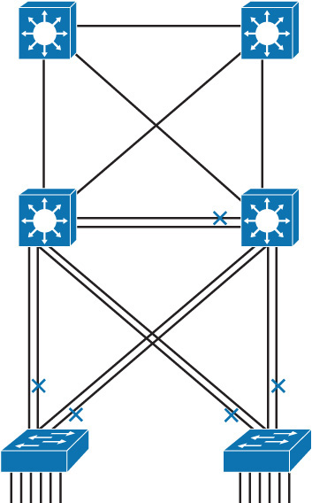
In Figure 3-23, traffic coming from several VLANs at 100 Mbps aggregate on the access switches at the bottom and need to be sent to distribution switches in the middle. Obviously, bandwidth larger than 100 Mbps must be available on the link between two switches to accommodate the traffic load coming from all the VLANs. A first solution is to use a faster port speed, such as 1 or 10 Gbps. As the speed increases on the VLANs links, this solution finds its limitation where the fastest possible port is no longer fast enough to aggregate the traffic coming from all VLANs. A second solution is to multiply the numbers of physical links between both switches to increase the overall speed of the switch-to-switch communication. A downside of this method is that there must be a strict consistency in each physical link configuration. A second issue is that spanning tree may block one of the links, as shown in Figure 3-23.
Figure 3-23 Network Without EtherChannel
EtherChannel is a technology that was originally developed by Cisco as a LAN switch-to-switch technique of grouping several Fast or Gigabit Ethernet ports into one logical channel. This technology has many benefits:
Keep in mind that the logic of EtherChannel is to increase the speed between switches, as illustrated in Figure 3-24. This concept was extended as the EtherChannel technology became more popular, and some hardware nonswitch devices support link aggregation into an EtherChannel link. In any case, EtherChannel creates a one-to-one relationship. You can create an EtherChannel link between two switches or between an EtherChannel-enabled server and a switch, but you cannot send traffic to two different switches through the same EtherChannel link. One EtherChannel link always connects the same two devices only. The individual EtherChannel group member port configuration must be consistent on both devices. EtherChannel technology only bundles ports of the same type. On a Layer 2 switch, EtherChannel is used to aggregate access ports or trunks. For example, if the physical ports of one side are configured as trunks, the physical ports of the other side must also be configured as trunks. Each EtherChannel has a logical port channel interface. A configuration that is applied to the port channel interface affects all physical interfaces that are assigned to that interface. (Such commands can be STP commands or commands to configure a Layer 2 EtherChannel as a trunk or an access port.)
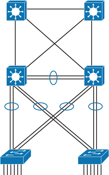
Figure 3-24 Network with EtherChannel
Using new technologies like VSS (Virtual Switching System) and vPC (Virtual Port Channel), a port channel can be created across two aggregation switches from the same access layer to provide better redundancy.
Keep in mind that EtherChannel creates an aggregation that is seen as one logical link. When several EtherChannel bundles exist between two switches, spanning tree may block one of the bundles to prevent redundant links. When spanning tree blocks one of the redundant links, it blocks one EtherChannel, thus blocking all the ports belonging to this EtherChannel link. Where there is only one EtherChannel link, all physical links in the EtherChannel are active because spanning tree sees only one (logical) link. If one link in EtherChannel goes down, the bandwidth of the EtherChannel will be automatically updated, and thus the STP cost will change as well.
On Layer 3 switches, you can convert switched ports to routed ports. You can also create EtherChannel links on Layer 3 links. Layer 3 port channels are discussed in more detail in Chapter 5.
Also, with technologies like VSS and VPC (which are discussed in more detail in Chapter 9, “High Availability,” you can create the EtherChannel between the access layer and two different aggregation switches.
EtherChannel can be established using one of the following three mechanisms, as shown in Figure 3-25:
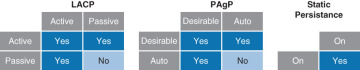
Figure 3-25 EtherChannel Modes Interactions
Link Aggregation Control Protocol (LACP) is part of an IEEE specification (802.3ad) that allows several physical ports to be bundled together to form a single logical channel. LACP allows a switch to negotiate an automatic bundle by sending LACP packets to the peer. Because LACP is an IEEE standard, you can use it to facilitate EtherChannels in mixed-switch environments. LACP checks for configuration consistency and manages link additions and failures between two switches. It ensures that when EtherChannel is created, all ports have the same type of configuration speed, duplex setting, and VLAN information. Any port modification after the creation of the channel will also change all the other channel ports.
LACP packets are exchanged between switches over EtherChannel-capable ports. Port capabilities are learned and compared with local switch capabilities. LACP assigns roles to EtherChannel’s ports. The switch with the lowest system priority is allowed to make decisions about what ports actively participate in EtherChannel. Ports become active according to their port priority. A lower number means higher priority. Commonly up to 16 links can be assigned to an EtherChannel, but only 8 can be active at a time. Nonactive links are placed into a standby state and are enabled if one of the active links goes down.
The maximum number of active links in an EtherChannel varies between switches.
These are the LACP modes of operation:
The following are some additional parameters that you can use when configuring LACP:
All the preceding options of LACP are optional to configure. Usually, defaults are the best to use. To configure any of these options, refer to your configuration guide.
Port Aggregation Protocol (PAgP) provides the same negotiation benefits as LACP. PAgP is a Cisco proprietary protocol, and it will work only on Cisco devices. PAgP packets are exchanged between switches over EtherChannel-capable ports. Neighbors are identified and capabilities are learned and compared with local switch capabilities. Ports that have the same capabilities are bundled together into an EtherChannel. PAgP forms an EtherChannel only on ports that are configured for identical VLANs or trunking. PAgP will automatically modify parameters of the EtherChannel if one of the ports in the bundle is modified. For example, if configured speed, duplex, or VLAN of a port in a bundle is changed, PAgP reconfigures that parameter for all ports in the bundle. PAgP and LACP are not compatible.
These are the following two PAgP modes of operation:
Negotiation with either LACP or PAgP introduces overhead and delay in initialization. As an alternative, you can statically bundle links into an EtherChannel. This method introduces no delays but can cause problems if not properly configured on both ends.
Before implementing EtherChannel in a network, plan the following steps necessary to make it successful:
Follow these guidelines and restrictions when configuring EtherChannel interfaces:
If the allowed range of VLANs is not the same, the interfaces do not form an EtherChannel, even when set to auto or desirable mode. For Layer 2 EtherChannels, either assign all interfaces in the EtherChannel to the same VLAN or configure them as trunks.
If you do not specify any protocol, it will be static binding. That topic is not within the scope of this book.
EtherChannel load balances traffic across links in the bundle. However, traffic is not necessarily distributed equally among all the links.
Frames are forwarded over an EtherChannel link that is based on results of a hashing algorithm. Options that switch can use to calculate this hash depends on the platform.
Table 3-6 shows the comment set of options for EtherChannel load balancing.
Hash Input Code
Hash Input Decision
Switch Model
Destination IP address
Destination MAC address
Source and destination IP address
Source and destination MAC address
Source IP address
Source MAC address
Source port number
Destination port number
Source and destination port number
To verify load-balancing options available on the device, use the port-channel load-balance ? global configuration command.
The hash algorithm calculates a binary pattern that selects a link within the EtherChannel bundle to forward the frame.
Default configuration can differ from switch to switch, but commonly the default option is src-dst-ip. It is not possible to have different load-balancing methods for different EtherChannels on one switch. If the load-balancing method is changed, it is applicable for all EtherChannels.
If only one address or port number is hashed, a switch looks at one or more low-order bits of the hash value. The switch then uses those bits as index values to decide over which links in the bundle to send the frames.
If two or more addresses or port numbers are hashed, a switch performs an XOR operation.
A four-link bundle uses a hash of the last 2 bits. A bundle of eight links uses a hash of the last 3 bits.
Table 3-7 shows results of an XOR on a two-link bundle, using the source and destination addresses.
Example IP Addresses
IPs in Binary
XOR Result
Forward Frame over Link with Index